My venture in hacking a fake vintage radio
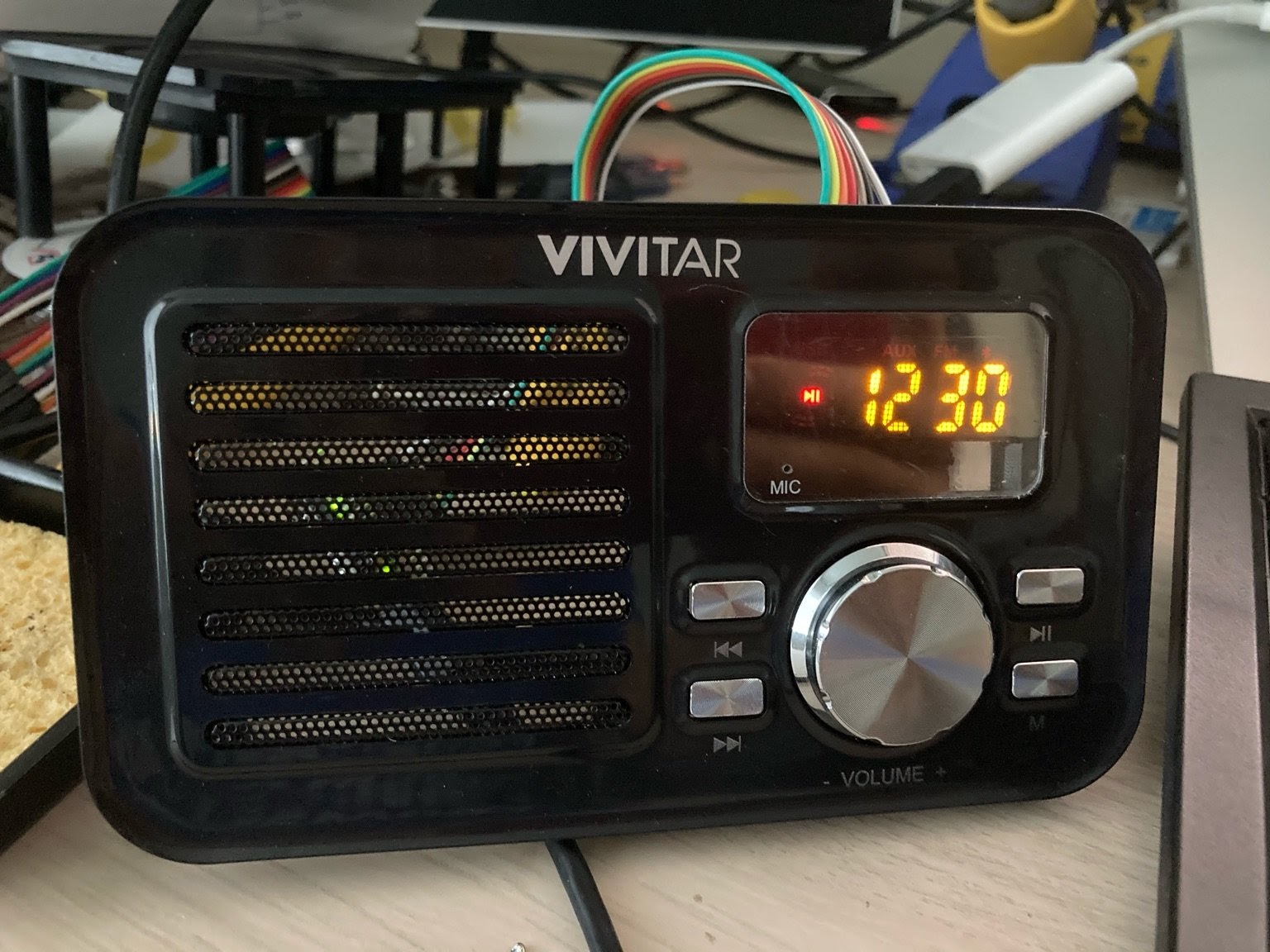
For a year or so I have owned a nice fake-vintage radio/bluetooth speaker that originally caught my eye for sale in a FedEx office. The front has a quite nice VFD-style LED to show the status, a volume knob and four hard buttons. It has Bluetooth, USB, AUX and FM input. The radio and bluetooth was not bad, but there was nothing to be impressed about. It was definitely not "smart."
I decided to hack it to make it a bit smarter: to do AirPlay and be a smart alarm clock and whatever else I could think of. Since it was inexpensive, I had nothing to lose and everything to win. I thought putting a Raspberry Pi 0 or something in it would be nice.
My original plan was to somehow figure out how to hijack all the external components and control them to make the front and back of the radio as neat-looking as possible. At least I hoped to hijack the speaker, the volume knob, and the buttons. The problem I foresaw was that those components are often not documented and there was little chance that I could get a datasheet for them. I was very worried that I might have to give up the fake-VFD LED screen.
It turns out that I had to spend a year hacking it on and off. Here goes.

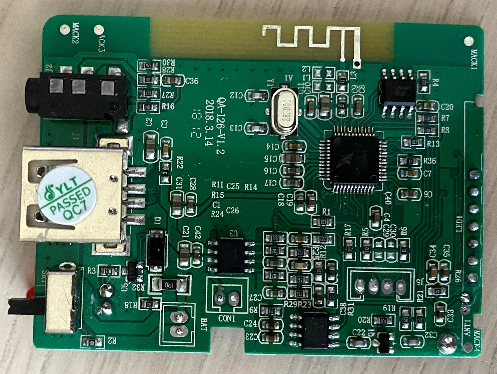
First, I gutted the radio and saw that it has a main PCB with the LED panel directly soldered to it.
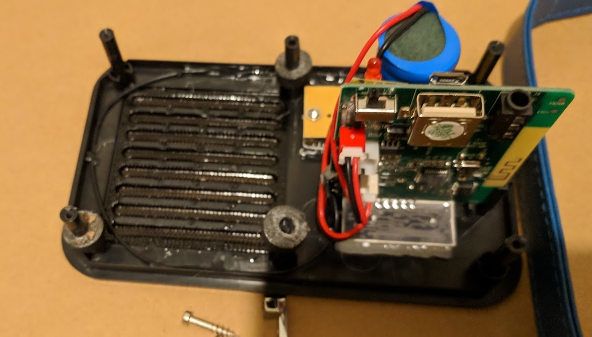
The chip on the PCB isn't something I recognized. Luckily, the knob and the hard buttons are on a separate breakout board and are connected to the mainboard via a connector.
The speaker
The speaker is also easy to deal with, as it is completely ordinary. It only required me to desolder it from the mainboard. As the Pi 0 has no built-in soundcard, I had to get a separate sound card for it.
Audio Injector Zero
Initially, I used the Audio Injector Zero that I have no use for normally. To save space, I decided to permanently sandwich the Audio Injector to the Pi 0. I also had to buy a cheap amp for it, as the sound card can't directly drive the speaker.
One little issue was that the sound card produces stereo input, and the amp is also stereo, but I only have one speaker. I needed to mix both channels left and right to that speaker somehow. To that end, I am sure a Linux guru could make it work with configuring the sound card in software. However, I am not extremely well-versed with how ALSA or Pulse Audio works. I just wired both channels left and right of the amp to one channel input of the amp to mix the channels. For power, the amp needs 5V input, so I siphoned the two power pins from the Raspberry Pi.
I was surprised when the amp produced a very annoying hum. The hum was extremely noticeable when the Pi is under load. I don't know exactly why this happens, but I spent way too much time on this with no significant improvement. Ultimately, I decided it's the cheap amp that was giving me a hard time, because it was way too noisy. I know the Audio Injector itself was okay because the headphones output was clean.
Google AIY voice hat
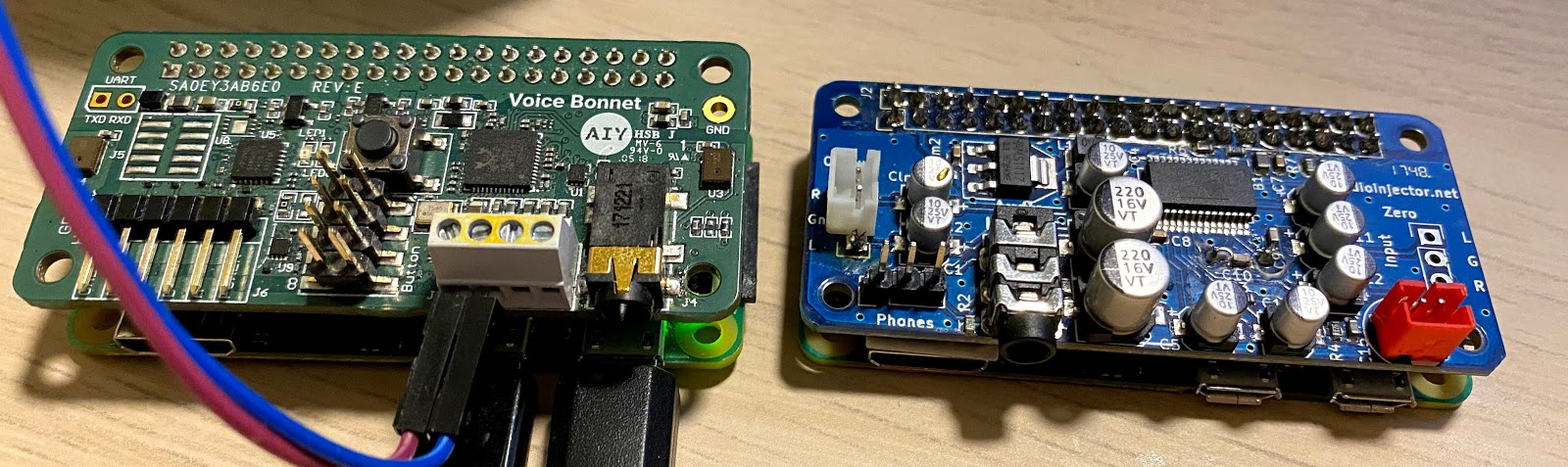
After giving up on the Audio Injector Zero + Amp solution, I tried a different route: Drive the speaker directly with the Google AIY voice bonnet hat. Because the Google AIY sound card doesn't provide an easy way to set up on a plain raspbian, I just got their distro and started from there.
The speaker was hum-free after switching to the Google AIY soundcard. The tradeoff was that the Google Voice Bonnet V2 sound card made the stack quite a bit thicker. It has a female row of pins soldered on it, so I couldn't solder it directly on top of the Pi Zero.
Multimedia buttons and volume knob
The front panel of the radio has two sets of elements: A knob of some sort to control the volume and four hard buttons. It has four wires hanging out of it. After I inspected the traces on the PCB, it was apparent that there is one common ground. The three other pins are for the buttons and the knob. All of the buttons are connected to a single pin, and the volume knob is connected to the other two.
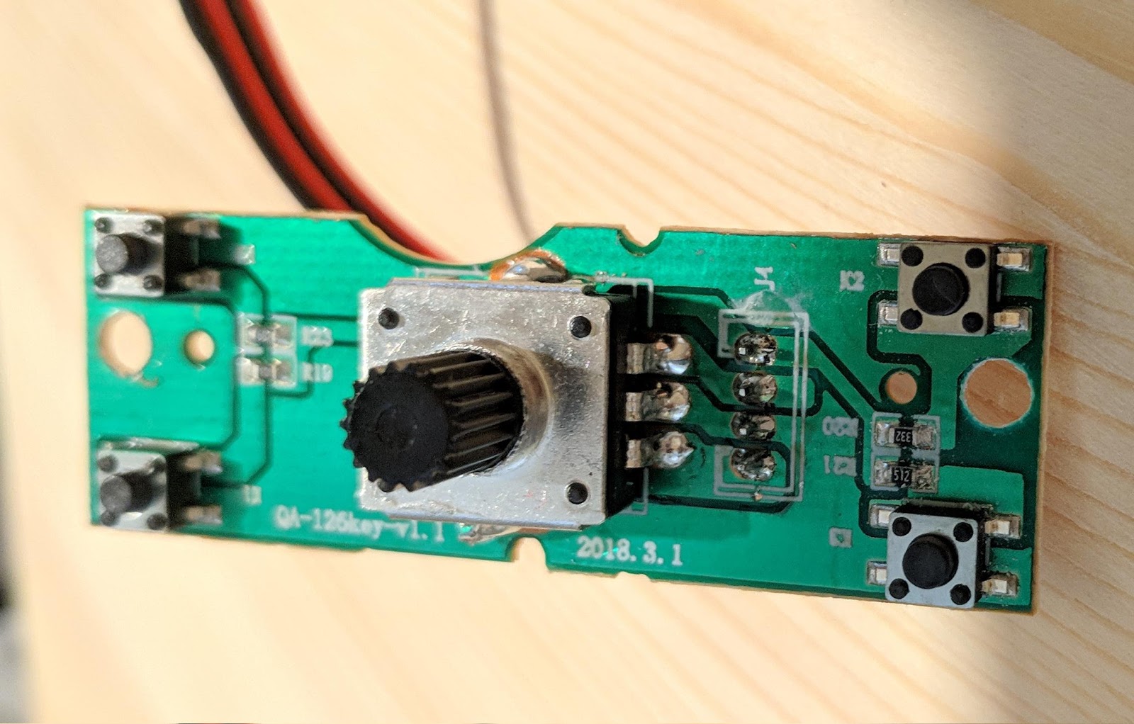
As a software person, I didn't know what the knob is called. Dr. Don Bindner suggested that the button might be a rotary encoder, and that turned out to be true. It seemed trivial enough to read the knob.
The buttons are more interesting. After poking around with a multimeter, it turned out that the buttons were tactile but each of them is connected in series to a different resistor. Then they all connect out to the same pin. The software in the chip scans the pin and figures out what button was pressed by sampling from an Analog-to-Digital (ADC) Converter reading. As the Pi has no ADC, we need something else that has an ADC to figure out what the button was pressed. Of course, I could as well hijack the tactile buttons and not have to deal with the ADC stuff but that seemed too aesthetically unpleasant for me.
I decided to pull out anArduino Pro Micro clone that I bought from China years ago. My reasoning for using the Pro Micro:
- The Arduino Pro Micro is super cheap: $2 cheap.
- Even if I could add an ADC to the Pi, I need to continuously read the ADC from the Pi. That is a pain in the neck. I can't guarantee the timings on the Pi without going to a lot of care.
- The Pro Micro can emulate a keyboard over USB, so the Pi can use triggerhappy to catch it.
So with that, I made my arduino sketch and it worked out. I wanted to emulate the Winamp-style buttons ZXCV for multimedia keys and UD for volume up/down. Later on, I was quite annoyed with it because the keyboard dumps the keystrokes to the terminal, and it could be bad. I decided to implement the keys as multimedia keys. Unfortunately, you need a HID library to implement multimedia keys. Luckily, there is a library called HID-Project to achieve exactly what I wanted. After some tweakings for debounce, I could get the volume knob and the buttons to work exactly as I expected:
void pressKey(uint16_t k, int d) {
  Consumer.write(k);
  if (d) {
    delay(d);
  }
}

void kbd_loop() {
  if ( millis() < debounce + debouncerMs) {
    return;
  }

  // Volume rotary handling
  boolean encoderA = digitalRead(encoderPinA);
  boolean encoderB = digitalRead(encoderPinB);

  if ((encoderA == HIGH) && (encoderB == HIGH)) {
    if ((encoderALast == LOW) && (encoderBLast == HIGH)) {
      pressKey(MEDIA_VOL_UP, 0);
    } else if ((encoderBLast == LOW) && (encoderALast == HIGH)) {
      pressKey(MEDIA_VOL_DOWN, 0);
    }
  }

  encoderALast = encoderA;
  encoderBLast = encoderB;

  // Multimedia buttons
  int pushBtnRead = analogRead(pushBtnPin);
  if (pushBtnRead > 900 && debounce != 0) {
    debounce = 0;
  } else if (pushBtnRead <= 264) {
    if (pushBtnRead > 200) {
      pressKey(MEDIA_NEXT, delayMultimediaKeyMs); // Next
    } else if (pushBtnRead > 150) {
      pressKey(MEDIA_PREVIOUS, delayMultimediaKeyMs); // Prev
    } else if (pushBtnRead > 115) {
      pressKey(MEDIA_STOP, delayMultimediaKeyMs); // Stop/M
    } else {
      pressKey(MEDIA_PLAY_PAUSE, delayMultimediaKeyMs); // Play pause
    }
  }

  debounce = millis();
}
I could test the Arduino implementation right on my development computer with xev so that was really nice.
The fake VFD LED screen
The screen was the part that I had the most doubt about being able to control, because I have never worked with such a device before. Before trying to reverse-engineer it, I tried to look up similar 7-segment LED screens online hoping to find something similar. Those screens often have more than 8 pins (1 for the ground, 7 for each segment, and some more to select the digit. This one is nothing like that: It has only 7 pins. I wanted to give it up and just buy another screen that has a datasheet to save myself from trouble but I couldn't find anything that would fit into the original cutout for the screen. So I had to bite the bullet and hack the LED screen (I had nothing better to do in the craziness of the pandemic).
General workings
There was no giveaway from the PCB what the ground pin for the display might be. I only had a multimeter in hand so what I did was set it to the diode tester mode. Then I probed pairs of pins to see what lights up. As luck would have it, I found out that each pair of pins lit up a different segment on the screen. So there was no common ground at all! I drew the screen and noted what pin pair light up each segment (excuse my nasty draft paper):
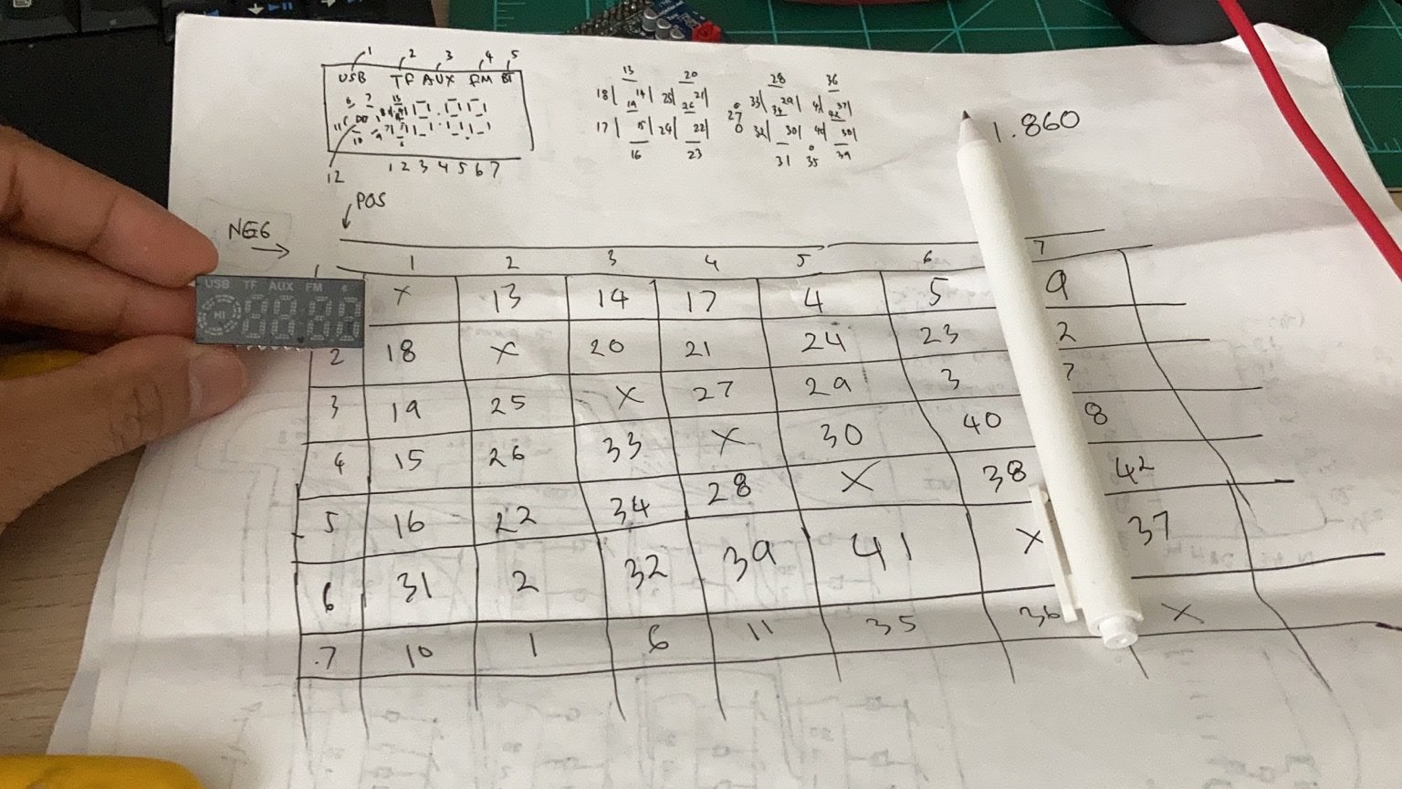
First, I was really annoyed because the screen is yet another custom device I had to reverse engineer. Then, it really impressed me that this screen is quite well designed for such a cheap device. There were exactly 42 segments on this LED screen! The number of different segments is exactly the maximum number of permutations between any 2 pins: P(7,2) = 42. After some more digging, I found out that this wiring scheme is called Charlieplexing. So each LED segment has a voltage drop of 1.860V, and my Arduino is 5V. I assumed a 20mA current and used a LED calculator and to figure out that I need to connect a 150K resistor to the LED. Because of the charlieplexing setup, I actually need half of that resistance for each pin (it will be apparent as you read on), so I soldered a 68K resistor to each pin.
Control the LED screen programmatically
The question then became how to control this LED screen programmatically. It was clear to me I can't possibly draw every segment by toggling the pins on and off in one whole sweep. Then I realized that I need to think of the LED screen like an analog TV screen. Thus, each of the pins can be thought of as a horizontal scanline – except they are not on the same “line”! This might be quite obvious to those who have dealt with CRTs in the past (which I have not), but it might be hard to imagine for those who grew up with LCDs.
Let's say I want to draw the screen with segment 17, 18, and 11 lit up. That means I have to do two sweeps. First, pull pin 1 to GND and pull pin 2 to V_LED to light up segment 18. Then, pull pin 4 to GND and pull pin 1 and 7 to V_LED to light up segment 17 and 11 at once. Do it fast enough, and my eyes won't be able to tell we are flashing them!
I had to set up a matrix of the screen buffer of what segments I want to draw. Then I needed a function that goes around and pulls one of the 7 pins to GND. It needs to pull whatever pins that are responsible for the ON segments in that matrix to VCC. Whatever pin that I give it VCC, it will need to have 150K resistance to prevent LED burnout. I needed half of that resistance on each pin (VCC and GND), because the GND pin rotates throughout.
The function that scans the LED screen buffer (scr_buf[SCR_SEGMENTS]) and draw one scanline in a loop:
static const byte SCR_LED_PINS_COUNT = 7;
static const byte SCR_SEGMENTS = 42;

static const byte scr_segment[SCR_LED_PINS_COUNT * SCR_LED_PINS_COUNT] ={
  00, 12, 13, 16,  3,  4,  8,
  17, 00, 19, 20, 23, 22, 11,
  18, 24, 00, 26, 28,  2,  6,
  14, 25, 32, 00, 29, 39,  7,
  15, 21, 33, 27, 00, 37, 41,
  30,  1, 31, 38, 40, 00, 36,
   9,  0,  5, 10, 34, 35, 00
};

void scr_draw() {
  // Set everything as INPUT, high impedance
  for (byte i = 0; i < SCR_LED_PINS_COUNT; i++) {
    pinMode(scr_led_pins[i], INPUT);
  }

  for (byte j = 0; j < SCR_LED_PINS_COUNT; j++) {
    if (scr_current_scan_i == j) {
      // Pull the current scanline HIGH
      pinMode(scr_led_pins[scr_current_scan_i], OUTPUT);
      digitalWrite(scr_led_pins[scr_current_scan_i], HIGH);
    } else {
      if (scr_buf[ scr_segment[scr_current_scan_offset + j] ]) {
        // Set the pins that are supposed to light up the segments
        pinMode(scr_led_pins[j], OUTPUT);
        digitalWrite(scr_led_pins[j], LOW);
      }
    }
  }

  scr_current_scan_i = (scr_current_scan_i + 1) % SCR_LED_PINS_COUNT;
  scr_current_scan_offset = scr_current_scan_i * 7;
}
To draw a number, the fact that I assigned each digit in the LED matrix consecutive segment numbers turned out to be very helpful. That way, I could write a simple, common function to manipulate the segments to display a digit at all positions: Everything I needed to change was the start segment.
static const bool scr_digit_segments[][SCR_DIGIT_LED_SEGMENTS] = {
  //A B C D E F G
  { 1,1,1,1,1,1,0 }, // 0
  { 0,1,1,0,0,0,0 }, // 1
  // and so on
};

static const byte scr_lcd_digit_start_segment[] = { 12, 19, 27, 35 };

void scr_draw_numer(byte number, byte digit) {
  if (number > 10 || digit > 3) {
    return;
  }
  byte start_segment = scr_lcd_digit_start_segment[digit];
  for (byte seg = 0; seg < SCR_DIGIT_LED_SEGMENTS; seg++) {
    scr_buf[seg + start_segment] = scr_digit_segments[number][seg];
  }
}
It worked:
In slow motion, it looks quite trippy:
Putting 1+1 together was not that easy
I wanted the Arduino Pro Micro to handle both the LED screen drawing and the multimedia buttons, because I didn't want to waste an extra Arduino board (Moreover, if I had used two Arduino boards I would have also needed a USB hub since the Pi 0 only has one USB port, and I don't think I have space inside the radio compartment for it). My loop function looks like so:
void loop() {
  kbd_loop();
  scr_draw();
}
Each procedure has to run pretty fast in the loop. How fast? For the screen to not flicker, I need it to refresh at 30Hz minimum. That means each “scanline” needs to take less than 4ms, as 1000(ms) / 30 (refreshes) / 7 (scanlines/refresh) = 4 ms/scanline.
But life ain't that easy! I could clearly see the flickerings in my LCD when I added kbd_read to the loop.
Optimizing the button handling procedure
I found out that the main reason that the loop is slow was because using the analogRead function to read the ADC hangs until the ADC until it finishes sampling the read. After googling around, I found a trick to set up the ADC so it continuously sample port A0 and I could read the ADC register whenever I want:
void kbd_setup() {
  // Blah...
  digitalWrite(A0, HIGH);
  ADCSRA =  bit (ADEN);
  ADCSRA |= bit (ADPS2);
  ADMUX =   bit (REFS0) | (analogPinToChannel(0) & 0x07);
  bitSet (ADCSRA, ADSC);
}

void kbd_loop() {
  // This returns right away
  unsigned int pushBtnRead = ADC;
}
Optimizing the screen drawing function
Although not as important, the scr_draw function runs in a loop and it's quite complex; it better be fast. I tried to give myself the exercise of accelerating the screen draw function. The pinMode and digitalWrite functions are not very performant. It turns out there's a better way to do it: you can write to a set of PORT and DDR registers to set the values of a set of rows at once. Because of the pin layouts of the Pro Micro, I only have as many as 6 of them on the same PORT, and one has to be another. I settled with 6 of them on PORTB and 1 of them on PORTE (pin 7), so the fast draw function looks like so:
static const byte SCR_PORTE_POS = 6;
static const byte SCR_PORTE_POS_MASK = 1 << 6;

void scr_draw_fast() {
  byte pinIo =    0; // Everything is INPUT
  byte pinVal =   0; // Everything is LOW
  byte currBit =  1;

  for (byte j = 0; j < SCR_LED_PINS_COUNT; j++) {
    if (scr_current_scan_i == j) {
      // Turn the current scanline on
      // Set it as OUTPUT HIGH
      pinIo |= currBit;
      pinVal |= currBit;
    } else {
      if (scr_buf[ scr_segment[scr_current_scan_offset + j] ]) {
        // Force Turn the segment on
        // Set it as OUTPUT LOW
        pinIo |= currBit;
      }
    }
    currBit = currBit << 1;
  }

  // Move the first LED pin to port PE6
  // Rest is PortB
  DDRB = (DDRB & 1) | (pinIo & B11111110);
  PORTB = (PORTB & 1) | (pinVal & B11111110);

  DDRE = (DDRE & ~SCR_PORTE_POS_MASK) | ((pinIo & 1) << SCR_PORTE_POS);
  PORTE = (PORTE & ~SCR_PORTE_POS_MASK) | ((pinVal & 1) << SCR_PORTE_POS);

  scr_current_scan_i = (scr_current_scan_i + 1) % SCR_LED_PINS_COUNT;
  scr_current_scan_offset = scr_current_scan_i * 7;
}
Now, everything worked and my screen (finally) no longer flickered!
Controlling the LCD screen from the Raspberry Pi
Next, I needed some way of communicating with the LCD screen from the Pi 0 to give it data to display. To make things easy, I set up a 115200 TTL serial connection and parsed the commands. For simplicity, the commands all have a fixed format and length CXNNNN. C is character C to signify the start of command, then X to signify command, then NNNN to signify the parameters. For example, to set the time to 14:00, I would have to send CT1400. It was quite trivial so I have nothing to write about it, other than this requires me to code up and track how many characters I have received and decide when to process the whole command. This task can be achieved through a quick-and-dirty state machine – a very important concept if you need to have any hope in tracking what state the system is in.
The only thing I have to admit was that I didn't understand how the switch statement works in C. Apparently, this is illegal:
static const byte SER_CMD_FIXED_LENGTH = 6;
byte ser_cmd[SER_CMD_FIXED_LENGTH];

void ser_process_command() {
  byte cmd = ser_cmd[0];

  switch (cmd) {
    case 'A':
        byte my_var = 0;
        break;
    case 'T':
        byte my_var = 1;
        break;
  }
  // blah
}
Can you tell why?
It was because I redeclared my_var. Apparently everything in the switch statement in C shares the same scope. We learn new things everyday!
Optimizing power consumption
I plugged in the contraption through a USB power sniffer-thingie and saw that the Arduino Pro Micro and the fake VFD LED screen consumped 0.02 A. Could I possibly squeeze more power from it? I tried everything I could with hardware timers/interrupts and nothing really drove down the power consumption.
In a desperate attempt to optimize the power consumption, I found out that there was a project called Low-Power. It uses the hardware watchdog timer to keep the microcontroller in a special low power state and that shaves around 0.01A from total power consumption. However, the wakeup interval is very weird, the fastest I could do was 15ms. That's four times slower than my slowest acceptable refresh rate (4ms/scanline). And rightfully so, it was really slow and made the screen flicker. But for some obscure reason that I don't understand, the timer fires every 15ms when there are no USB data lines connected. However, as soon as you have USB data lines connected, the timer fires at 1ms. I don't know why so, but it worked to my advantage, so I couldn't complain. My loop function looks like so:
void loop() {
  // SLEEP_15MS sleeps exactly for 1MS when you have USB data lines connected???
  LowPower.idle(SLEEP_15MS, ADC_ON, TIMER4_OFF, TIMER3_OFF, TIMER1_OFF,
    TIMER0_OFF, SPI_OFF, USART1_ON, TWI_OFF, USB_ON);

  kbd_events_process();
  scr_events_process();
  ser_events_process();
  _millis += 1;
}
Note that the millis() function no longer returns the correct number of milliseconds passed. So, I had to manually count the number of milliseconds in a variable and make sure that each of the procedures I called doesn't consume more than 1 ms. I had to eliminate all calls of delay() in the code, because that would not only make the screen flicker, but also surely mess up the counter. That was also tedious and inconvenient but quite trivial.
And with that, I was able to drive down the power consumption of the Arduino to 0.01A. Fantastic!
Setting up the Pi
I need the Pi as my fake radio to do three things for now:
- Play my songs through Airplay from my iPhone: Shairport-sync is an excellent project.
- Handle multimedia buttons: Triggerhappy does the job.
- Tell the Arduino the time, as the Arduino doesn't know itself.
Items 1 and 2 are pretty self-explanatory. For part 3, I was getting really lazy and sloppy. So while I could do things more efficiently and less error-prone, I just assume that the device comes up on the Pi as /dev/ttyACM0 and this simple cron script syncs the time from the Pi to the Arduino every hour and at startup. I have found the Arduino to be surprisingly accurate, it doesn't drift more than a minute after 24 hours, so it doesn't need the Pi to tell it the time that often.
#CTXXX sets the time
#CC1000 displays the current time on the fake LED screen
TIME_NOW=$(date +'%H%M'); echo CT"${TIME_NOW}"CC1000 >/dev/ttyACM0
Then the rest is just to put the Pi into the enclosure and enjoy my smart fake-vintage radio!
Conclusion
Please press F to pay respects to the fallen fake radio.
That was way too much work, but in the end, it is a labor of love and I am really happy with the result!
My source code for the Arduino portion can be found on my vivitar-radio-hacks Github repository. I hope it was fun for you to read it as it was fun for me to do it.
I thank Dr. Bindner who helped proofread this post. By the way, I also know that Dr. Bindner is writing an Arduino book that is supposed to be complete soon!